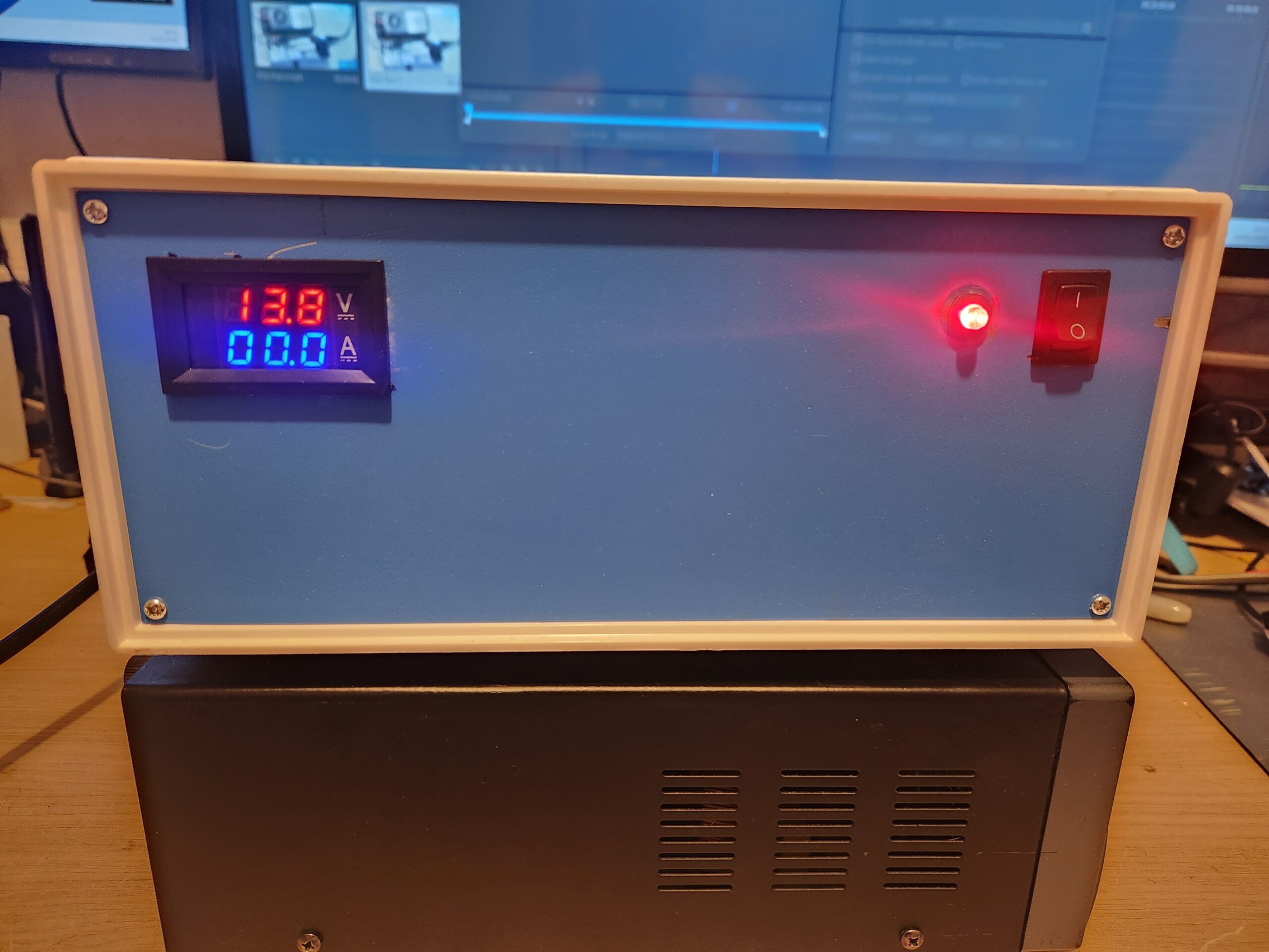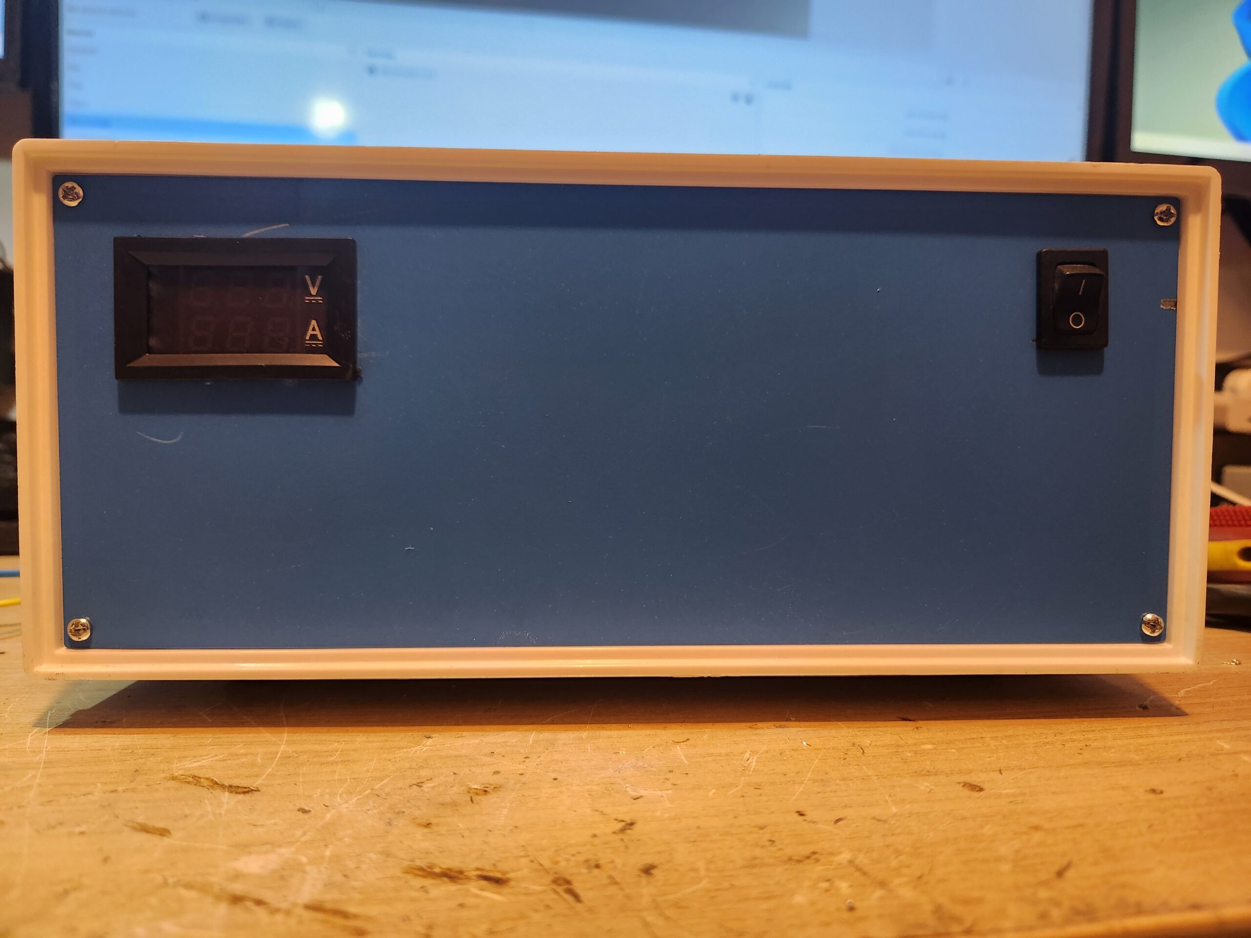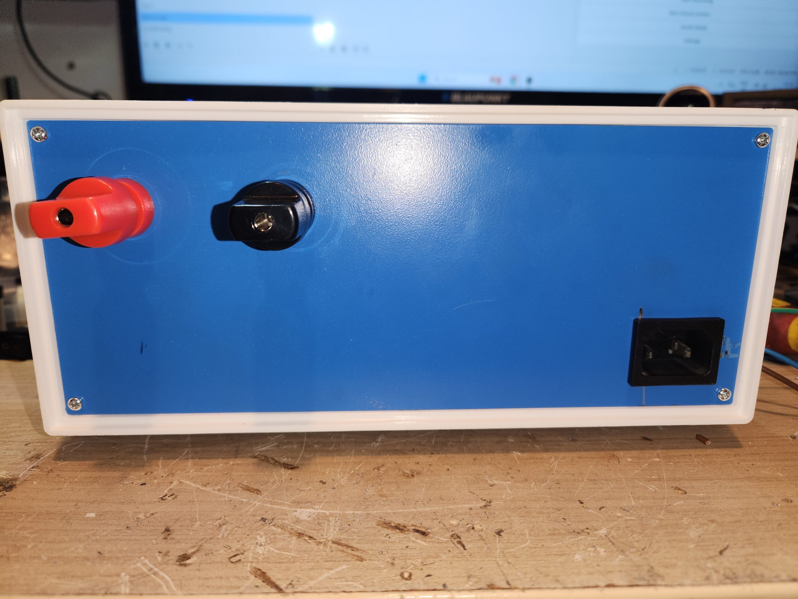
100A 13.8V Shack Power Supply
Why this project?
Commercial 100A Amateur Radio Power Supply can be hundreds
of pounds, while enterprise server power supplies are made for current power
hungry components with a need of several amps. This project will unveil how I
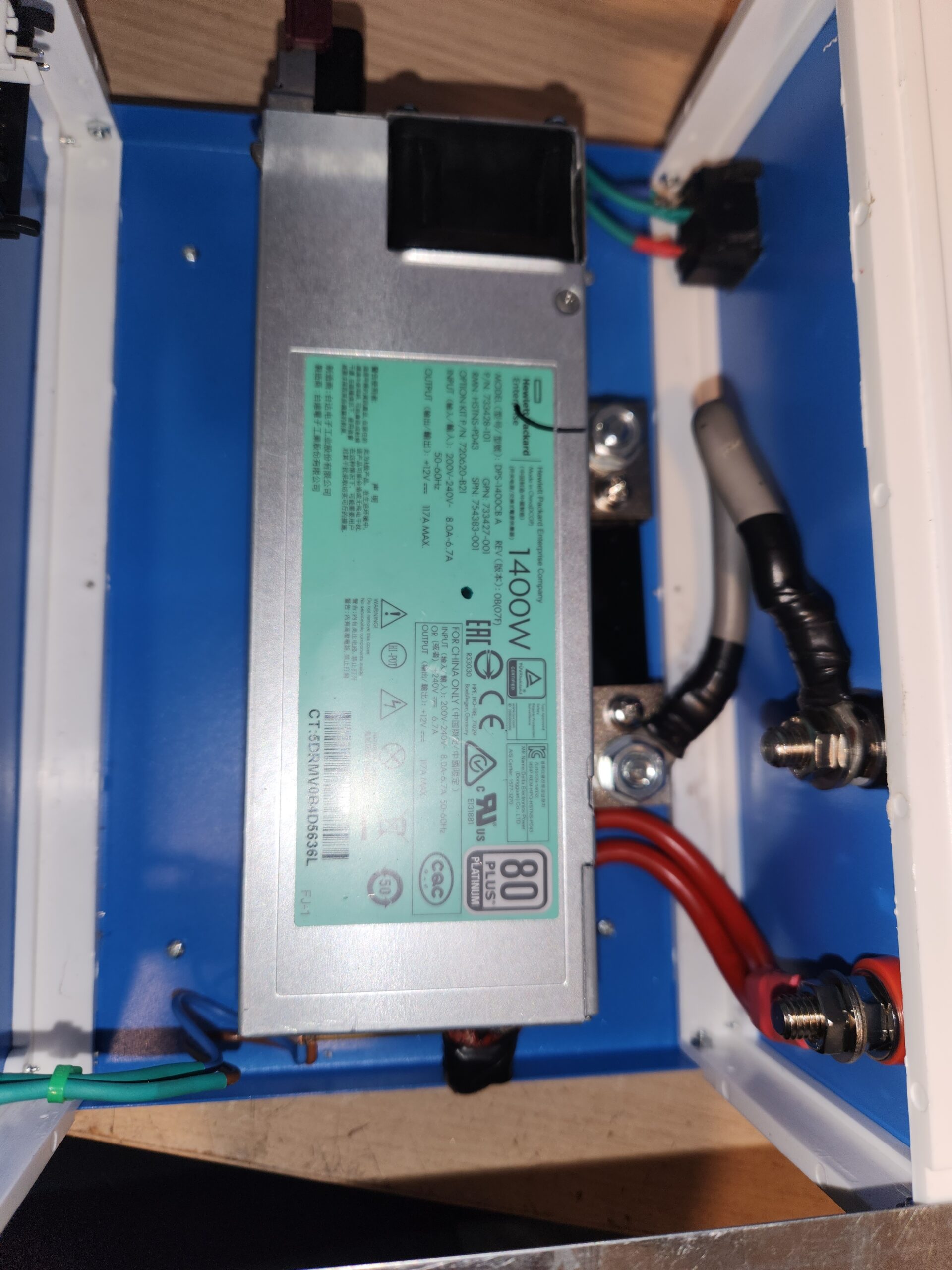
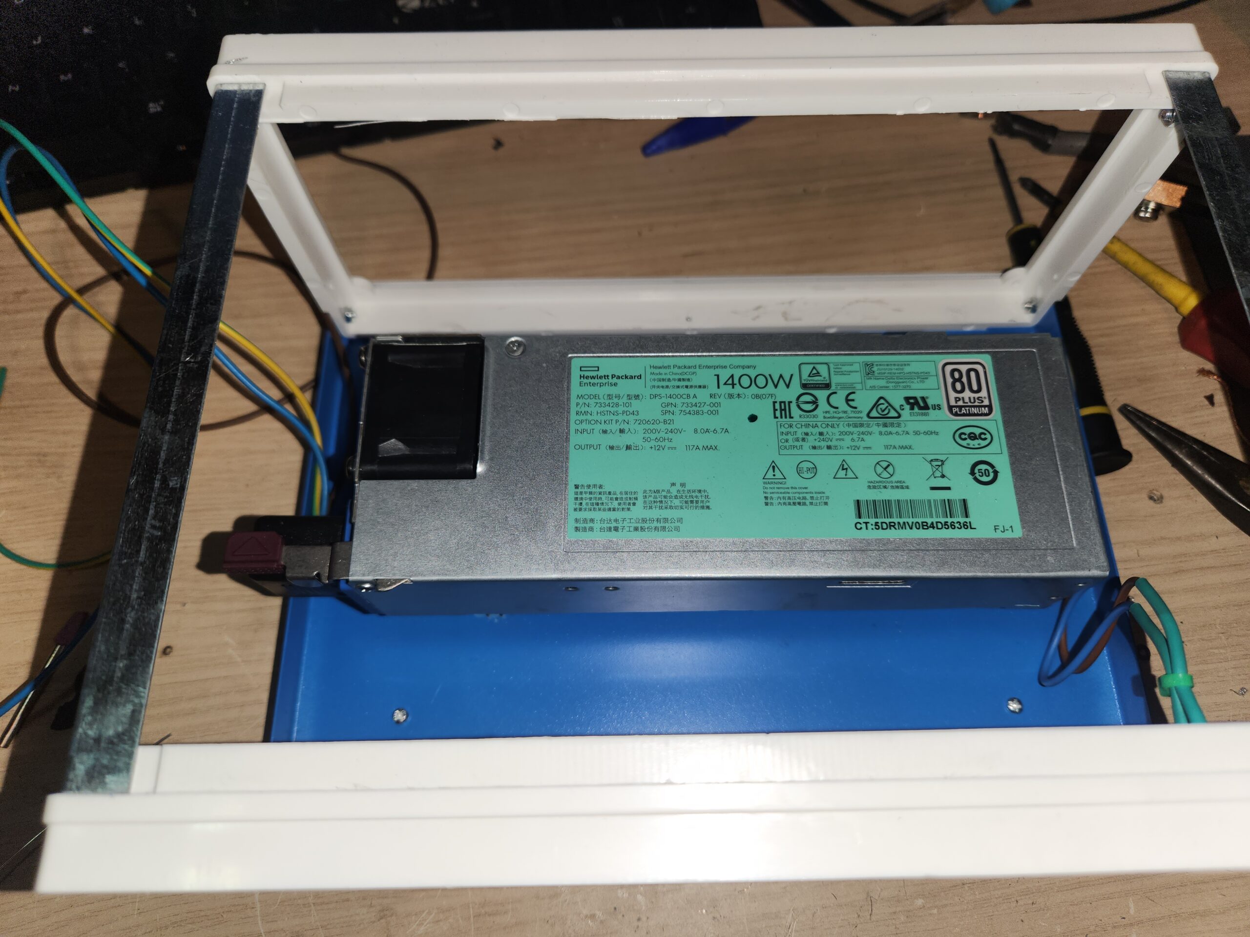
have modified an HP HSTNS-PD43 1400W enterprise server power supply into a
reliable 13.8V DC power source with a current capability of 100A for my amateur
radio station. This power supply is not only destined to power my HF station,
but it was also the reason why I decided to make the 110A programmable
electronic load to test its capabilities at 100A. You can see the full build
process on YouTube, where I also demonstrated all modifications and the final
tests and assembly.
100A 13.8V Shack Power Supply
The Story Behind the Build
Motivation for this build came from a long-awaited desire
to modify some server power supply into something more useful for my personal
shack. Not only these commercial power supplies capable of 80-100 amps are
outrageously expensive, but their appeal is minuscule in comparison to the
enterprise-grade power supplies that are exceptionally reliable and can be
acquired at a low cost.
The idea for this build came from a fellow amateur radio enthusiast from my local radio club. I told him about my plans for converting a server power supply into a shack power supply and he mentioned that he actually had two HP HSTNS-PD43 power supplies at home. He was kind enough to give me one of his to experiment with. That was all the push I needed and I decided to start working on the build right away.
Gathering the Parts
To turn this power supply into the shack power supply I
needed the following components:
• Metal case to host the power supply
• 22kOhm and 6.8kOhm resistors for the voltage modification
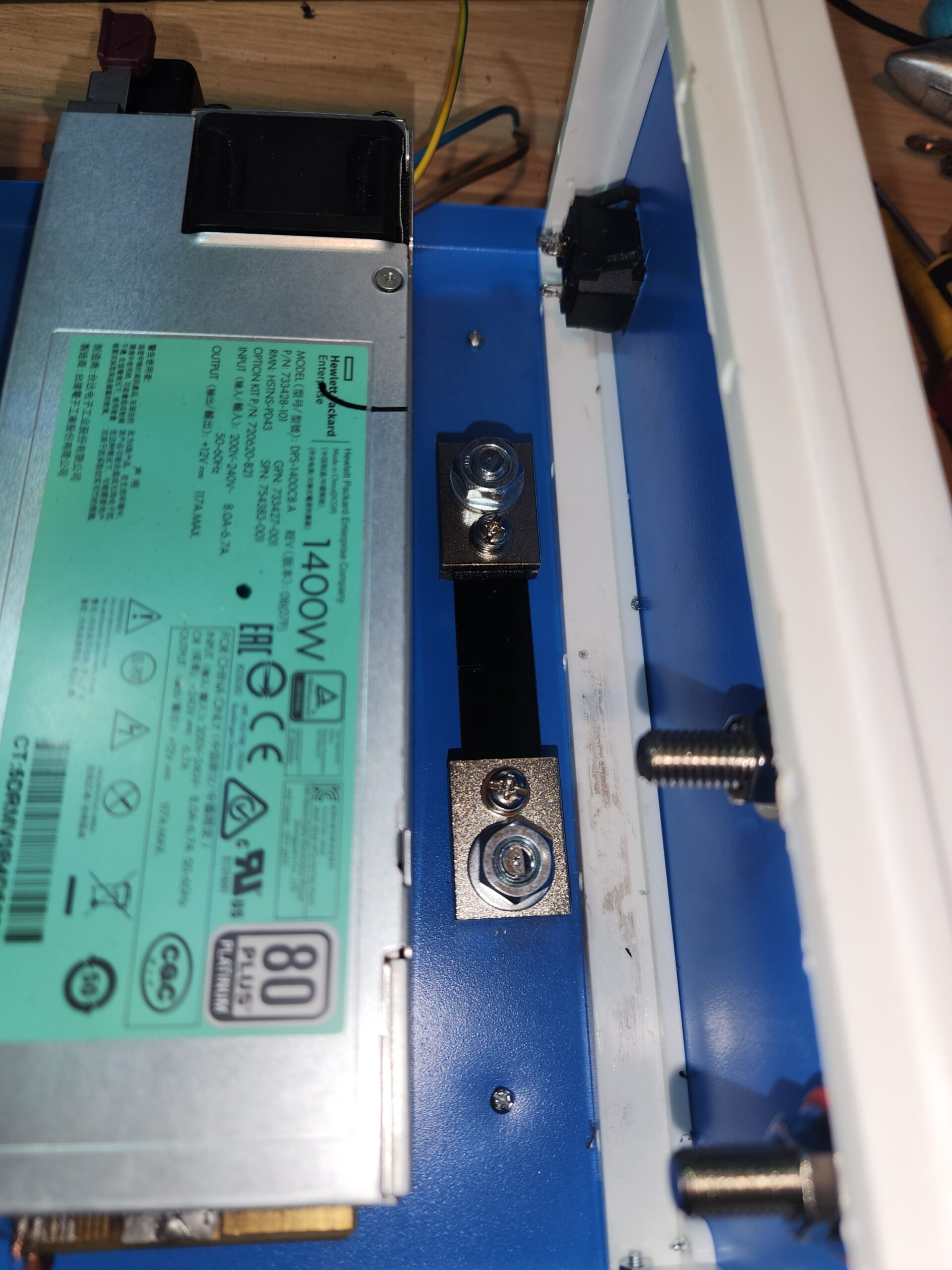
• Volt/Amp meter with 100A shunt
• Power LED indicator
• 50A terminals
Fortunately, I had all the required components to finish
the build, excluding the metal case, resistors, volt/amp meter, power indicator
LED, and 50A terminals that I had to purchase separately.
Modifying the PSU
The first step I had to tackle was the modification of the
power supply itself to reach the desired 13.8V. The modification process
involved the installation of the 22kOhm and 6.8kOhm resistors on the power
supply’s PCB. This step was by far the most complicated part of the build and
it took me a lot of time to R&D the optimal resistor placement.
During the resistor installation I’ve accidentally detached
a SMD resistor from the board and had to order a spare one before proceeding
with the rest of the work. After the modification was complete, the power
supply was working flawlessly and was able to provide a stable 13.83V output.
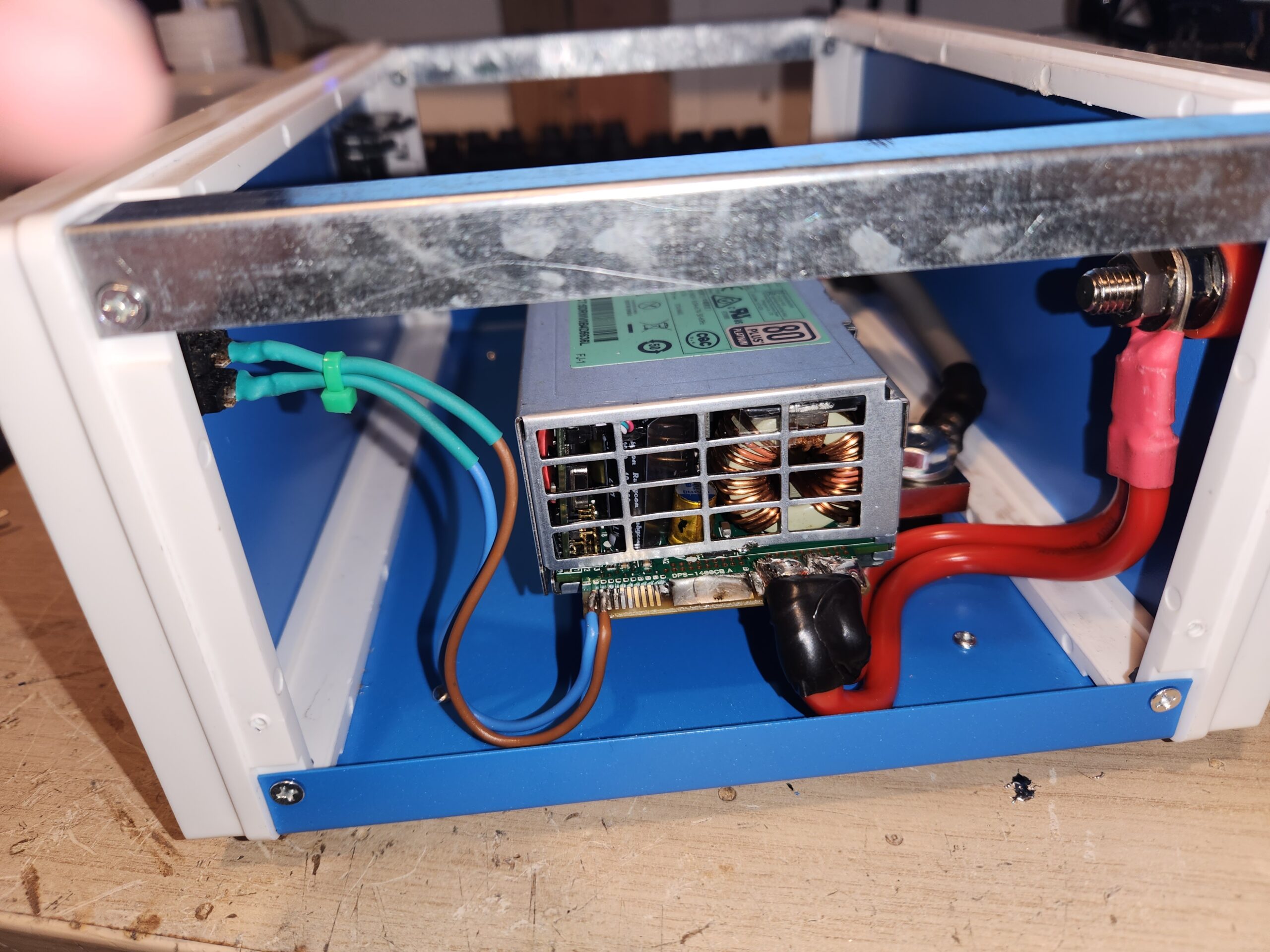
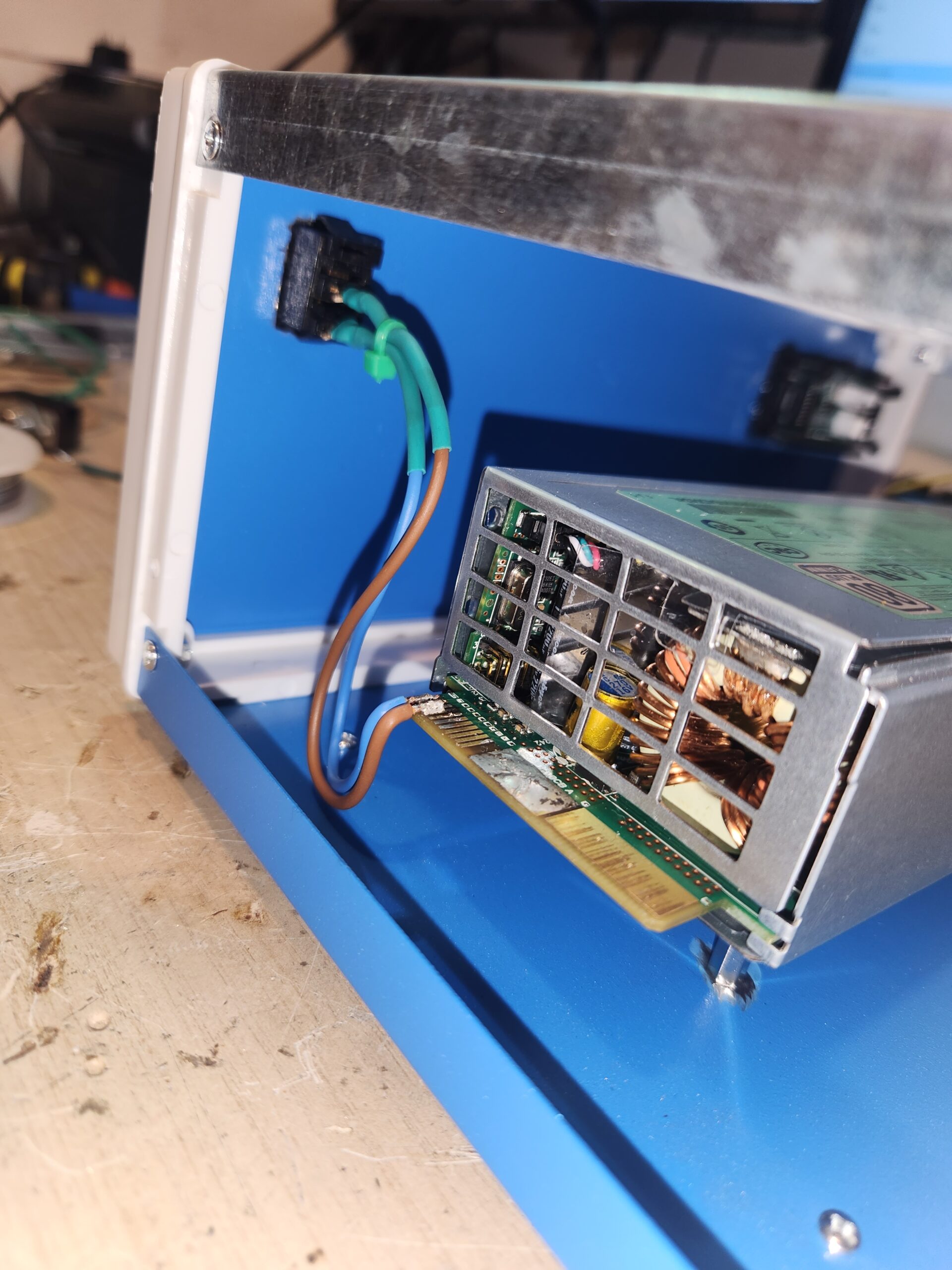
The next step was to re-install the power supply into its
original case with some modifications to improve the airflow. I’ve also added
three small legs to the case to ensure that the power supply will not touch the
floor of the new enclosure directly.
Designing the
Enclosure
The creation of the enclosure began with the front and rear
panels. I did not start cutting any materials right away. Instead, I have
printed the front and rear panel templates on paper, marked the approximate
placement of the volt/amp meter, power switch, power LED indicator, IEC mains
inlet, and the high-current DC terminals.
Once I was satisfied with the layout, I proceeded to mark
these locations on the actual aluminum panels with a permanent Sharpie marker.
After that, I’ve used a Dremel tool to cut all the required slots, holes, and
outlines for the enclosure panels. It was really satisfying to see how the
enclosure started taking shape.
Wiring Everything
Together
After finishing the enclosure, the last major step was to
wire all the components together. The hardest part about this step was to
solder the thick DC power cables to the power supply’s thick copper tags. These
tags were extremely heat absorbent and they would suck all the heat away from
the soldering iron tip making it impossible to solder the cables to the power
supply. Fortunately, after all the hard work, everything was ready and I moved
on to the final testing.
Final Tests and Assembly
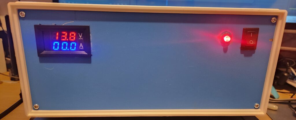
I flipped the power switch and my heart skipped a beat. The
volt/amp meter turned on and displayed a beautiful 13.8V of electricity with
perfect functionality. I could not believe it!
This power supply has become my reliable companion and the
main power source for my amateur radio station. It has proven to be
exceptionally reliable and has powered my HF station with no issues. Most
importantly it did not introduce any RF noise to the HF bands. This turnkey
power supply build was a real challenge but a great experience for me and I
consider it to be a complete success. Not only has it become one of the most
useful projects in my shack, but it has also prompted me to build the 110A
constant current load to test the capabilities of this power supply at 100A.