
110A Constant-Current Electronic Load
Building a laboratory grade constant-current load capable of testing high-current power supplies up to 110 amps.
Status:  In Development
Why build a load tester
After completing my 100A 13.8V shack power
supply, I discovered I had no way of reliably testing it anywhere close to its
maximum output. A bank of resistors or car headlamps may certainly draw
current, but wouldn't provide an accurate, variable constant-current testing
platform
This project aims to address that by creating
a
constant-current electronic load capable of
testing 13.8V supplies across 0A to 110A, becoming my new piece of test
equipment for not only power supplies and batteries but other high-current DC
projects in the workshop.
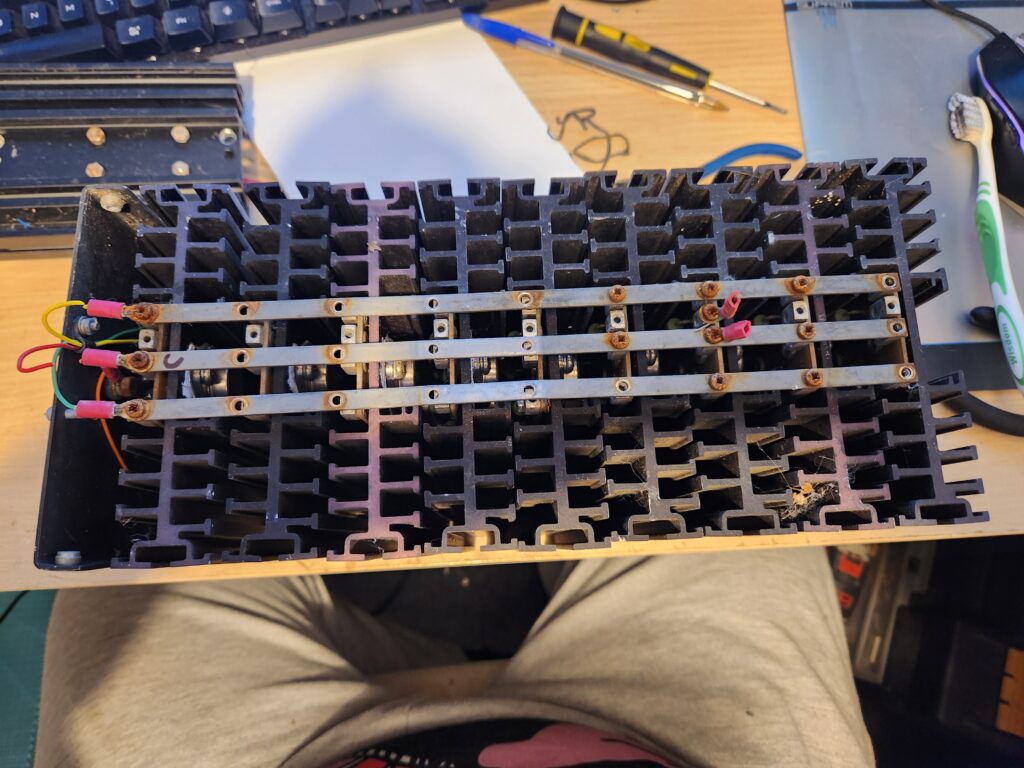
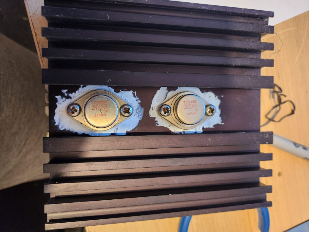
The heart of the design is an array of 9
genuine Farnell modules. Each module houses 2x 2N3055 power transistors, each
using a pair of 0.5Ω 50W ballast resistors in parallel, achieving current
sharing. Combined together, the 18 transistors provide a significant power
stage, capable of dissipating huge power while being individually balanced.
Specification
The Control System
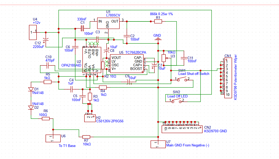
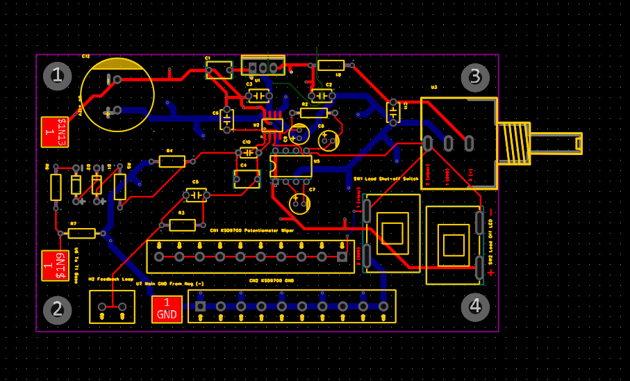
Rather than using a set of manual resistor
banks, the load will be fully analogue and employ closed-loop current
regulation.
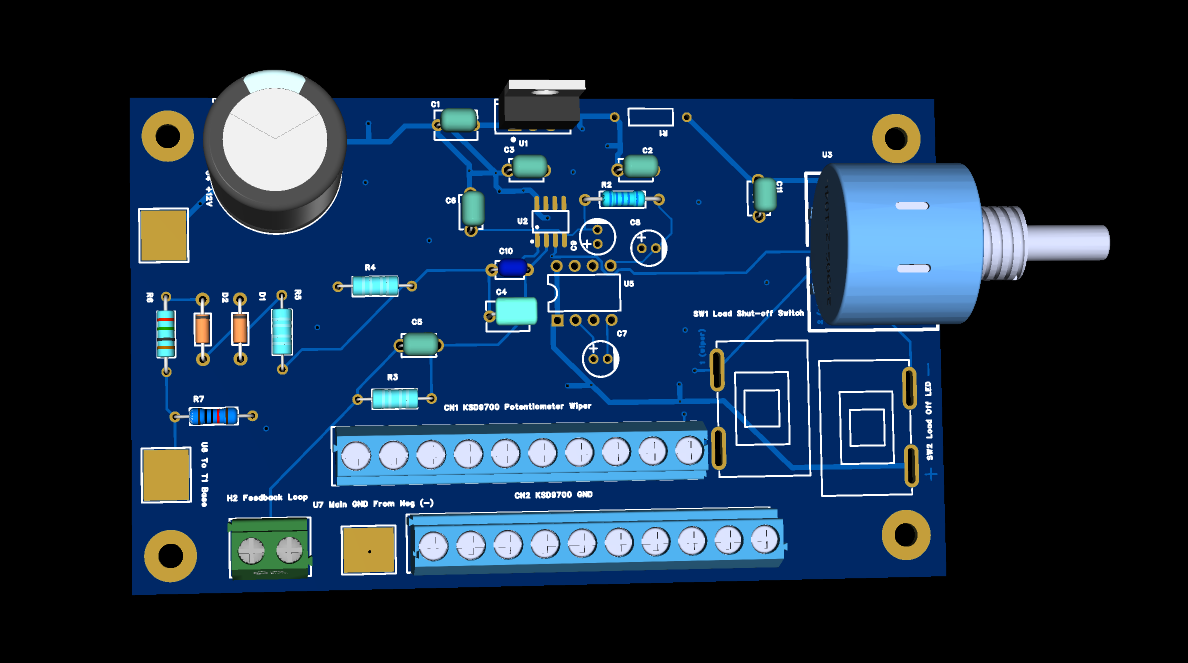
A Mean-Well LRS-450-12 provides power for the
control electronics, cooling and front-panel instrumentation. The controller is
built upon an OPA2188 precision op-amp, comparing the desired load current with
the voltage developed across a 150A / 75mV shunt.
A 10-turn Bourns 3590S precision potentiometer
sets the desired current, allowing extremely fine control from almost zero amps
up to the full 110A range. A TIP142 Darlington transistor provides the base
drive for all 18x 2N3055 transistors, simultaneously.
In addition to the above, the controller also
employs:
L7805CV precision 5V reference supply
TC7662B negative voltage generator for the
op-amp
Shielded twisted-pair feedback wiring
Single-point star grounding
Automatic base pull-down during power loss
One feature I'm particularly pleased with, is the inclusion of an Enable Load switch. Rather than a standard power switch, this switch simply forces the reference voltage to 0V, starving the transistors of base current and reducing the load to zero, without having to remove power from the controller.
Cooling System
Dissipating over a kilowatt of heat requires
serious airflow, therefore cooling has been designed from the beginning, rather
than an add-on.
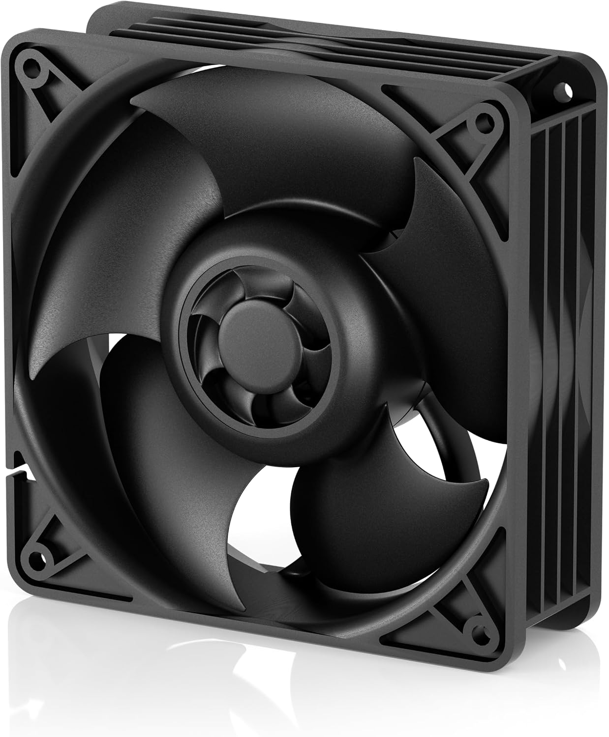
The load will utilise 6 Arctic S12038-8K
high-performance fans in a 3 push / 3 pull tunnel configuration, with 3 fans
forcing airflow through the heatsink assembly and the rear 3 extracting it,
providing a controlled airflow through every Farnell module.
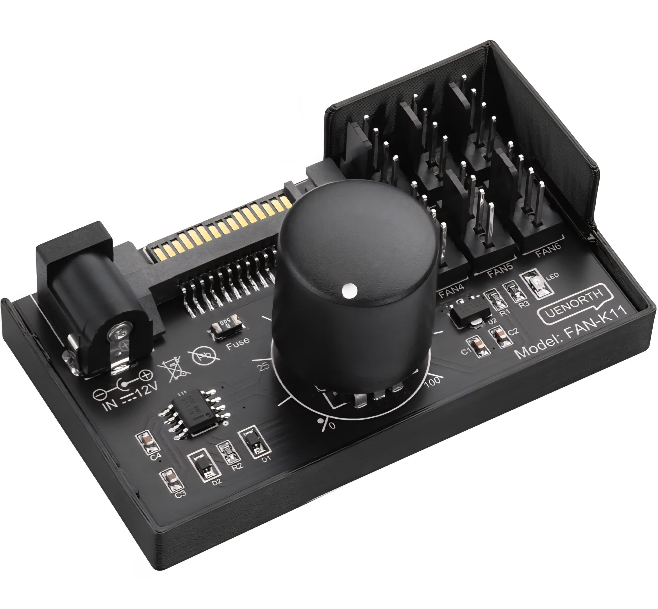
A Uenorth Fan-K11 six-channel PWM controller
runs the fan, allowing the cooling system to be quiet on low loads, but provide
maximum airflow during high-current testing.
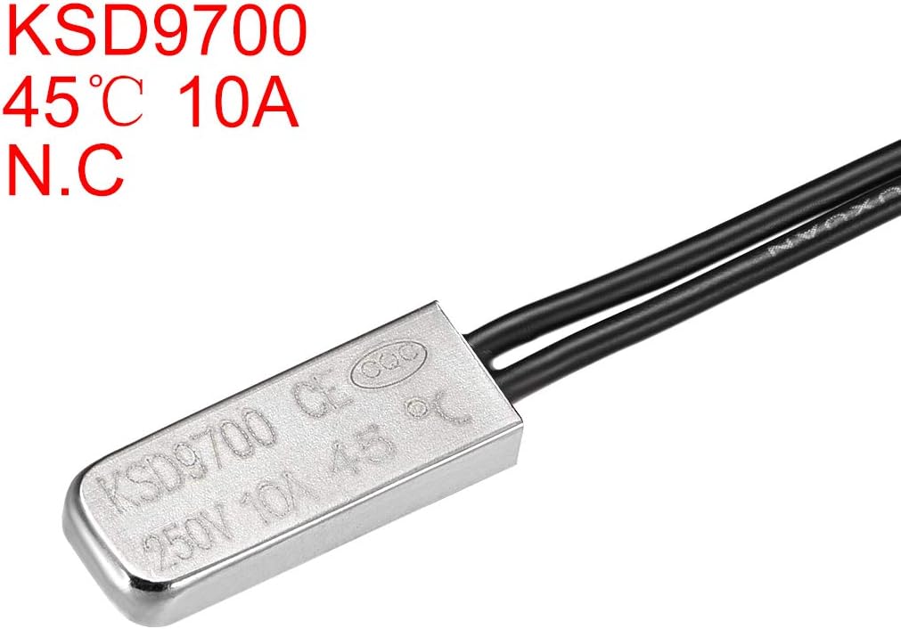
Just as important is the safety aspect, with
every heatsink hosting its own KSD9700 thermal switch, with a 10th protecting
the TIP142 driver stage. All 10 switches are wired in parallel with the Enable
Load circuit, such that any overheated module will immediately shut off the
load. A front-panel LED will illuminate, whenever thermal protection has been
engaged.
High-Current Busbar
Design
Although the Farnell modules include copper
busbars, they were never intended to carry 110amps continuously.
Rather than a single busbar, the finished
design employs a star-wired current distribution system, with each of the 9
modules connecting to a set of heavy-duty positive and negative common busbars
via individual 2.5mm² conductors with crimped and soldered terminals.
Current flows through the common negative
busbar, feeding a 150A / 75mV precision shunt, serving as both:
Accurate current measurement
The single DC star-ground reference for the
entire instrument
By bringing every ground connection back to
this single point (the controller, voltmeter, PWM controller and feedback
loop), the measurement circuitry is isolated from the high-current return
paths, providing stability and reducing electrical noise.
The Chassis
This is one of the biggest design decisions I
have to make. The aim is to fit everything inside a Bud Industries RM-14213 4U
rack enclosure, fitted with the optional C-14243 internal chassis. If
everything proves too large, I'll redesign everything to use a larger
enclosure.
The internal chassis will be modified with
three large openings to allow the front fans to push air directly through the
heatsink fins, with matching openings in the rear panel allowing the extraction
fans to pull the heated air completely out of the enclosure, creating a
front-to-back cooling tunnel, similar to enterprise server hardware.
The finished unit should resemble professional
laboratory equipment, yet be totally home-built.
Earthing Philosophy
One area I wanted to get right, was earthing.
The AC mains earth is bonded to the chassis at
a dedicated grounding stud, immediately beside the IEC inlet. From here, a
single 6mm² earth conductor connects to the DC star ground, located on the
input side of the shunt.
All other ground within the instrument
(controller PCB, fan controller, thermal protection, panel meter and feedback
wiring) returns to this single star-ground point, avoiding ground loops, and
ensuring safety and accurate current regulation.
Project Status
This project is currently under construction.
The mechanical layout has been designed, the Farnell modules have been tested,
and the controller circuit has been developed. The next step is to complete the
chassis, busbars and cooling system, before full calibration and load-testing
up to 110A.
The ultimate goal is to create a
professional-grade electronic load capable of accurately testing my 100A shack
PSU and future high-current amateur radio projects.